Monday 29 March 2021

Raleigh Twenty: Front hub service, removing rust chrome wheels

The 46T 165mm crankset off the BSA 20 is utilitarian, but good looking, after the rust is removed and the chrome polished. I especially like the little "Nottingham Knight" stampings. Virtually unworn teeth:


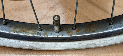
OK, it's cottered, but I'll make sure to assemble it with anti-seize. I tried removing some rust with Aluminium foil and water, and while it works, it can cause scratches, probably because solid particles can get dragged about under the metal foil. I prefer using 0000 wire wool with WD40. That removes rust quickly and minimises scratching. Here are some before and after shots:

And another one:


In this one, the bottom part of the front hub has been cleaned, but not yet the top part. You can see the yucky grease solidified into varnish. Easily cleaned with WD40 and a small piece of green plastic scourer. This is probably the first time the hub has been opened since 1978! 


Note also the 3 cross spoke pattern, but interestingly, the crossing spoke goes over the first, second AND third spokes, not under the third, as is often the case on larger wheels with 3 cross lacing. And here's the other side, all clean, ready for balls (10 BB each side of 3/16"):

Like the chainset, there's a lot of character in these late 70s Raleigh Sturmey Archer front hubs. They are actually very well thought out in my opinion, as I'll describe further below. 


Here are the parts. Note that both cones have a small flange turned on them, but only one cone, the moveable one, has flats to make it a nut. That's because it is used to adjust bearing play - while the hub is on the bike! The other cone on the axle is intended to stay fixed - there's a stop on the axle to prevent it passing further along the thread. Note that neither cones have locking nuts (90mm across the outsides of the cones). 


You have to hand spring the front fork slightly opening the front dropouts a tad to let the flanges of each cone fit in. I measured my forks at 87mm across the insides, so that's a decent 3mm spring. Once in though, the hub will stay put, held by the cones, even before you put the nuts and washers on the outside of the forks. So, the clever bit is that you can adjust bearing play by sliding a cone spanner inside the fork on to the flats of the cone nut, and turning slightly. Once set, tighten the outside washers and axle nuts, and that holds it all down. Quite neat and clever and they run pretty smoothly (even this one despite the wear groove in the cone). Just remember to put the fixed cone on the right (drive side) of the bike, because on the other side, there will be a natural tendency for the bearing to tighten, which can be harmful to it. As an experiment, assemble and hold the axle ends in your hands, give the wheel a spin and fiddle about - it's easy to see the natural tendency of the bearing to tighten up when the fixed cone is on the left, and the natural tendency to loosen with the fixed cone on the right. But don't worry, they won't loosen in use, because the external nuts lock everything in position. 

For the inner tube side surface of the rims, I simply spray a bit of WD40, brass wire brush and then a quick going over with a slightly coarser steel wool. Wipe it off with a small cotton bath towel, and hey presto, clean insides ready for rim tape. For the Sturmey Archer AW I merely oiled it using a cheap plastic pipette and 1:3 mix of car transmission fluid to 5W engine oil. The pipette allows a small measure to be squirted easily into the oil port. That three speed tickety tick! As they say, AW stands for Always Works...


So here they are, shiny chrome wheels, and hubs, bling bling! After a bit more tightening and truing, I'll dress them in new white-wall shoes. 

Wednesday 24 March 2021

Raleigh Twenty Steerer Restrictions and Bottom Bracket

There are two mechanical restrictions on the steerer assembly of the Raleigh Twenty, here, a BSA 20. 

VERTICAL RESTRICTION

As promised in an earlier post, here's a photo underneath the steerer, looking between the front forks: 

You can see the wire wrapped around the main brake bolt. The wire also attaches to the stem:


The wire could be copper or some kind of bronze. Here's a close up of wire twisted up around a pin in the stem:

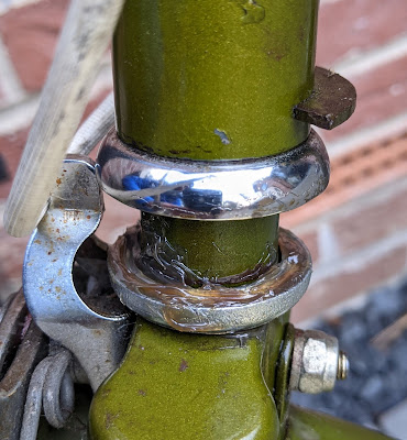
The wire's function is to prevent the stem from being completely pulled out of the steerer tube. At the top of the first photo at the start of this blog post, you can see the bent plate chromed bracket on the brake bolt, sitting snug against the front of the forks. 

ROTATIONAL RESTRICTION

Here is another view of that bracket, this time from above:

If you don't know what the bracket's for, then you may think it to be some kind of "English decorative curio", or a basket attachment! But I hope this picture helps you to understand the function of the odd shaped bracket. As the handlebars are turned, the bracket "folded hands" hits the metal welded C shape plate behind the head tube. So, the steerer stop bracket and that welded C shape plate on the back of the headtube together provide a mechanical restriction to the range of movement of the forks. 

I believe that both of these steerer restrictions were intended as safety features, but I'm not certain of that.

CRANK REMOVAL & BOTTOM BRACKET SERVICE

I also took off the cranks for servicing the bottom bracket. The non-drive side cotter pin came off easily. But the drive side one was stuck like a pig. Removing a seized cotter pin has got to be my most unfavourite bike mechanic job! I had to drill it out, and it was a real struggle. Here is the first pilot hole: 

You've got to use something as cutting fluid (I used 3in1 oil). I then followed up with wider diameter drills and finally after much hammer dynamics, got the *#*£$@! out (one day later!). 

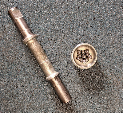
And I finish with some photos of the BB shell, axle and cups, apart and reassembled. The axle is 14.2cm long, and measures about 6cm between cones. There are 11 balls of 1/4" on each side. It's clear that this bike was not much used, which makes it a great candidate for a clean up and service. Restoration using as many of the original parts as possible.


I think the drive side cup is welded in - in any case, I didn't bother trying to remove it. Now I just need to find some new cotter pins, which as far as I can tell are 3/8" in diameter. Whether or not it's considered right, I WILL use some copper anti-seize when I fit them. 

Wednesday 17 March 2021

Servicing a Raleigh Twenty 20 Headset: Nylon Bushing, Crazy Design?!

The headset arrangement on a Raleigh 20 is a little bonkers in my view. The bottom part is a conventional ball bearing race, and really quite good. The top half is the bottom half's Frankenstein brother. In this sequence of photos I'll show you details, as I open up this BSA 20 for inspection, cleaning and lubrication. (For replacing the top part, see this previous post). Here's the front view:

Now remember that the stem has restricted vertical movement in the steerer, because of a wire loop tie inside at its foot. I don't have a photo of that here, but when I get the wheels and mudguard off next, I'll try to take some pictures. For now, note that the stem can be lifted up a little, but cannot be taken out. Below is a pic of the top part of the headset. From the top: stem, top lock nut, light bracket, second lock nut (hidden by the light bracket), stem-steerer clamp, and a metal top cap:

So, straight away you can see that the clamp squashes between the lock nuts above it and the head tube bearing below it. This is a less than ideal situation for good bearing preload. Let's open up from the top:

With the nut off and light bracket lifted, you can see the second lock nut properly. Unscrew that second lock nut and raise the parts: 

I've taken off the clamp lever in the photo above. Note that the bolt has a square flange and can be removed to allow the clamp to lift up easily over the threads. You can see the metal top cap has indentations on its lid. That's what I mean by not ideal for bearing preload - the clamp interferes with the even downward force of the lock nuts. And beneath, you can see the top edge of the infamous nylon bushing. How does the clamp join the stem to the steerer tube I hear you ask? Well, because of this cut out


You can see how the clamp edges push on the sides of the T shaped cut to press the steerer on to the stem tube. Obviously, the designer was trying to deal with how to raise and lower a stem without having to deal with expander bolts as in a regular quill stem. It just about works, but I would not describe it as an elegant solution! This time, I was not replacing the top bearing, merely inspecting, cleaning and lubricating. I used a drop of thick gearbox oil around the inside of the nylon bushing to help the steerer tube rotate inside it. Don't put too much in there, because you need the stem to clamp to the steerer and excess lube might mess that up.

Finally, I serviced the bottom race, which is fiddly without taking the stem out, but can be done. Just make sure you have a sheet on the floor to catch any loose ball bearings when you first lift it up. When I did that, the ball race was dry, with a bit of hard stuck grime on the race that needed to be removed. Below, is a photo of the bottom bearing opened up, the 25 balls of 5/32" removed, cleaned, greased up ready for the shiny balls to be placed on the lubed cup. 

The bottom cup is pretty chunky as you can see, and merely sits on the fork crown. In this example it was not a tight friction fit, as compared to a regular crown race on a typical fork. 

In a previous post (search on Raleigh Twenty Project) I showed some pictures of the headset replacement that I did on a blue Triumph Trafficmaster 20.  Although I kept good photos of the nylon bushing and bottom race, I didn't make a thorough a photo record of how I fitted the 1" threadless top bearing. So when I do the next one, I'll take more photos of how to get rid of that nylon bushing and replace it with proper bearings.

This time, though, I was only inspecting, cleaning and lubing. It was enough to improve the steering of this particular "shopper bike". While it's better than before, I know it can be improved a lot more, but that would require this stem to be untied from its base, chucking the clamp, fitting a new quill stem, which probably means new handlebars, etc. By the way, another approach is to completely replace the forks and headset (the head tube diameter is relatively conventional traditional size). 

However, my plan for this bike is not really modernisation, but rather rejuvenation with judicious restoration. Which is what working on this cycle and riding it gives me a bit of!

Saturday 23 March 2019

Dawes Impulse, Reynolds 531, Shimergo

Here's a comfortable ride that I recently acquired via an internet sale:


And here is what it looked like on purchase, before I sorted out the handlebars, changed the front wheel, and fettled the brakes:

Here are extracts from 1990 Dawes catalogue:

And some blurb and data:

Rest of the catalogue data:

In my sample, it seems that quite a few parts have been changed. However, I think the original chainset Exage Biopace 52/42T 170 and brake levers were still on. The gearing was a bit insane, with a Shimano Uniglide 6 speed hub, and lowest gear of 42-21T (53"). But, it shifted well. So, I changed the bottom bracket from the cone and axle cotterless to a sealed cartridge Shimano 110mm unit, and the chainset to a 46/36T 175. This gave much more manageable gears with a low of 36-21T (45").

And here's a photo of it today, with the new chainset, saddle, seatpost, tyres and the as purchased front wheel back on:

Next step is to get rid of the DT shifters in the most convenient way possible. I love DT shifters, but one has to admit that bar-mounted shifters are better. The rims are grey anodised Mavic-MA40 and are virtually new - definitely not what was on the machine as shipped by Dawes. These rims have been rather nicely laced on to decent refurbed hubs - Campagnolo in front and Shimano FH-RM50 ND (6 spd Uniglide) at rear. Not only that, the 6 speed system is shifting well, so I'm minded to leave it as is.

I measured the pitch (distance between sprocket centres) as best I can, and made it 5.5mm. Consulting references on Shimergo - btw, I'm really annoyed with the CTC and their shoddy reproduction of Chris Juden's article on the subject - tables are chopped-up/wrong/missing! - I'm minded to try simply fitting second hand Campagnolo 8 speed Ergo shifters. The undoctored chart (Table 4) indicates that with the 'hubbub' rear mech clamp tweak, there would be ~0.03mm discrepancy in cog pitch, so it ought to work.  I have some DT stops already in my bike bits. The 1990s 8 speed Campagnolo shifters that I've seen for sale often have splits in the brake hoods. I'll probably have to get new hoods, but that's not a big deal. Even if I'd not bothered with a Shimergo mod, I'd have had to buy replacements for the current tatty and discoloured gummy ones. They are supposed to be white, but they've disintegrated to beige.

However, the rear mech does not appear to have a hubbub-able cable clamp! That said, old style Campagnolo 9 speed shifters give a pitch of 5.49mm, whereas the new style ones of same speed provide 5.26mm. This is going to be interesting...

Excited to try this and blog about it later.

Friday 27 July 2018

Chuck's Tech Opinion: Bicycle pumps, pressure gauges: Can you trust their measurement?

Can you believe in the pressure measurement of your pump or tyre pressure gauge? Here are a couple of handy gauges: Schwalbe digital gauge on the left and an analogue AccuGage on the right:


Digital Schwalbe: 35g
Analogue AccuGage: 86g
Many pumps, both big and small, have gauges these days. L to R in the photo below: Lezyne Floor Drive (steel), Topeak Joe Blow Sport and Topeak Turbo Morph G: 

So, with these pumps and gauges, I decided to gather some data to see what I could find out. Using a large volume presta valve MTB tyre (Maxxis Ardent), a Challenge Grifo cyclocross tyre, and a Continental Ultra Sport road tyre, I set various pressures using the Joe Blow Sport. I chose that one simply because it was new and the gauge nice and clear: 

The protocol was to set a pressure with this pump, and then with the other pumps and gauges to check what reading they gave. So the Joe Blow acted as the reference value. Of course, we don't know which of these gauges gives the best absolute measurement. 

Absolute means closest to the actual correct standard unit measurement. Contrast with precision, which is about how repeatable a measurement is. 

Here is a close up of the gauge on the small Morph: 

I didn't expect the small dial to allow precision in measurement. And finally, the Lezyne dial, which has a crack in it: 
The clear issue here is what looks like a zero error. With no tyre attached to the pump, it reads about 20psi. (I could not find a way to zero its gauge). I did my best to minimise air escape while switching between gauges. 

OK, with that description, here are the results in a graph (units on each axis are psi):

The x=y line is the Joe Blow "reference" value. You can see that the AccuGage ('+') and the Schwalbe digital ('solid dots') followed that line very well up to about 50psi. For higher pressures, the Schwalbe still followed that line well, but the AccuGage fell a bit below it (~5psi at 80psi). Remember, we've just randomly selected the Joe Blow to act as the reference. The Morph ('open circles') seems to be reading generally 5psi higher than Joe Blow reference and the two stand alone gauges. Most obviously, the Lezyne ('x') reads consistently ~20psi higher than the Joe Blow, AccuGage and Scwhalbe. 

The other thing that came out during this test is that ease of use is a big deal. The Lezyne and the Joe Blow are the easiest pumps to use. The Morph is rather awkward in comparison, and reading the dial is not easy. Both of the stand alone gauges require a bit of practice to use efficiently. With the knurled nut of the Presta valve slightly open, you push the gauge down over the valve and the instrument measures and holds the reading. Out of the two, the AccuGage was much nicer to use because it was easier to slide over the knurled nut of the valve. This seems to be down to its external shape and the size of the opening. The needle stays where it is until you press the very convenient air release button. No batteries, no switching on or off. The Schwalbe has a smaller hole, so tends to contact the knurled nut on a Presta valve more and allow air to escape. Also, the oval shape doesn't give the hands as much purchase on the tool. Perfectly functional, but compared to the AccuGage it was a little irritating during use. On the other hand, the digital gauge is lighter and fits better in a jersey pocket.

It seems reasonable to conclude that because three gauges were pretty consistent with each other (Joe Blow, AccuGage analogue and Schwalbe digital) that these are the closest to measuring the absolute pressure value. That conclusion is consistent with the Lezyne simply suffering a +20psi zero error.

I will continue to use the Lezyne, despite what appears to be its lack of absolute accuracy. All I need to remember is that it reads 20psi high consistently across the usual tyre pressure ranges. This is purely a systematic error. The Morph gauge reads about 5psi high, but its dial has poor resolution anyway. Its utility is in its portability and the fact that for its small size, it can pump up pretty hard. For off road and remote use (e.g. with a pocket pump), the stand alone gauges would get the nod. I'd use the Schwalbe when I need to be able to differentiate between 1 or 2 psi (cyclocross) or if I need to carry a gauge in my pocket. That said, the ease of use of the AccuGage is a big attractor. 

Yes, you can trust your pressure gauge measurement, BUT only if you really understand what it's telling you!

Saturday 28 April 2018

Park Tool Derailleur Hanger Alignment tool DAG 2.2 - Review

Why didn't I buy this earlier?! Yes, it's relatively expensive, but within a year I've used it on 6 bikes and am very happy with the results. Why? Because it improved rear mech changing performance hugely. In some cases, transforming a noisy, crunchy, chain-scruncher to a beautifully efficient "click-whirr"! In my view the tool has easily paid its way already.


I had bought the tool for when the bike may have pranged on something, or fallen on to the drive side, putting the hanger visibly out of alignment. But to my surprise, it's been very helpful for new bikes too. Which tells me that alignment is not always (hardly ever?) checked when a new bike or frame goes out the shop-door to a customer!

The purpose of the thing is to ensure that the rear mech is well-aligned with the sprockets on your back wheel. More precisely, the tool ensures that the plane of the cassette's sprockets is normal to the rear mech fixing bolt hole axis in the derailleur hanger.

If you have trouble adjusting rear mech cable tension to get smooth shifting in both directions, or an otherwise sub-standard rear transmission, just take a quick look at the alignment of your rear mech pulleys and the sprockets. If they are not coplanar, then use this tool to fix it. In the past, I tried realigning by hand, and while it can improve things, the tool allows you to align accurately. Once that alignment is decent, the rear mech can do its thing properly. Suddenly, your transmission works beautifully.

Although it's a simple-looking tool, I can see that a lot of thought has gone into its design. There are various factors to consider in the design of such a tool:

1. Robustness and longevity. The lever needs to be stiff enough, and the attachment to the hanger strong enough. This is because the lever is used to manually bend the hanger. No problem here with the Park Tool. The lever is strong and the rotating bolt is a good tight fit in the heavy housing. Moreover, the threaded end bolt can be removed (it has an allen key socket in it) and replaced. Here's a photo of the main bolt pin removed (need to remove a grub screw):


2. Must fit. Look at a bunch of bikes in a shop, and you'll see a variety of positions of the derailleur hanger bolt hole with respect to rear dropouts, wheel axle, etc. So, the tool has to be able to attach to all these types. I've had no issues with this so far, and I think this is because the part of the tool that houses the bolt is fairly narrow diameter.

3. Ability for the indicator to be moved in and out without losing the setting. The tool has to be used while on the bike (because the hanger is on the bike!). Therefore, the indicator has to be moveable to get around at least, the chain stays and then any other parts hanging about, such as racks, mudguard arms, or even the derailleur itself (if all you've done is unbolted it and let it hang free). The indicator on the tool achieves this with a small knob, and small O-rings to keep the setting as you move it in and out.

Tips and Learnings


1. What I've learned recently, is that even small improvements in hanger alignment can cause big improvements. These kinds of misalignment are not that easy to see with the eye alone, but the tool can detect it. I suppose this is because the indicator looks at the rim positions which is a long distance from the sprockets.

2. I put something on the wheel in the bottom dead centre position, e.g. the tyre valve. Throughout the testing and alignment process, I ensure that the valve remains in that spot.

3. Take off the rear mech. If the hanger is removable, unbolt it and clean it. Grease the bolts and refix it securely before you start the alignment procedure. Sometimes, the issue is not alignment, but rather hanger tightness!

3. CAREFULLY screw the tool into the mech hanger hole - really really really don't want to cross threads here!

4. The procedure I've used that has worked well starts with first using the indicator to look at the top and bottom of the wheel rim to work out which way the hanger is bent in or out from the wheel. (This requires sliding the indicator housing, because the rear mech hole is not in the wheel centre). Then look at the back of the wheel rim and front of the wheel rim (which requires maneuvering the indicator around the chainstay) to figure out which way the hanger is toed in or out from the wheel's plane.

5. Then, spend a few seconds (minutes?!) to visualize how the hanger is aligned with respect to the wheel in your mind BEFORE you bend anything.

6. Make the first bend. So far, I have gone for a horizontal and vertical approach: (1) with the lever horizontal to correct toe-in/out, and (2) with the lever vertical to correct push-in/pull-out. In other words, I get the alignment satisfactory with the lever vertical or horizontal, then get the alignment satisfactory in the other direction (lever horizontal or vertical).

7. I try to minimize the number of bend attempts, because metal fatigues! A couple of mm difference in the indicator positions at the rim doesn't seem to make much impact, so it doesn't seem worth bothering to get mm perfection. Remember that whatever the "gap" is on one side, you only have to bend the hanger half that amount to get it aligned.

8. After correcting both vertically and horizontally, I go back to 4 above and quickly recheck all is good and that the hanger plane is close to parallel to the wheel plane.

9. The knob on the indicator slider and the small O-rings on the indicator work fine. However, I've found that the O-rings will disintegrate over time. I need to get more of them, but at least O rings are easy to find online and cheap.

10. Clean and grease the main bolt pin (see photo above), or perhaps a drop of oil every now and then to keep the bearing smooth. A good idea to keep it easy to screw into the mech hanger hole.

Here's a video from Park Tool of the thing in use.

Park Tool have done a super job with this tool and I recommend it highly. Just get a small bag of replacement O rings.

Saturday 18 June 2016

Electronic Shifting: Di2 Road Bike Build

Finally, I've decided to take the plunge and build myself a road bike with Di2. Why? Three reasons:
  • Easier. I acquired a frameset last year which I think will be easier to hook up with electronic shifting rather than cables. Furthermore, I cannot find suitable cable guides for both the drive side chainstay and the BB shell - which looks like this:
  • Cheaper. I've worked out that I can do it for a few hundred quid less than it would cost to buy a ready made Di2 bike of equivalent quality. That's partly because Shimano Ultegra 6870 Di2 groupsets can be found for ca. £860 these days. 
  • Curiosity! What's the fuss all about? What are they like and how do they perform over time? 
As you can see, none of these reasons are to do with any disillusionment with standard cable operated gears. 

Hopefully, I'll do a better job than the chap who put this bike together:


So, watch this space, as I gather all the bits and undertake the project this summer.