There are two mechanical restrictions on the steerer assembly of the Raleigh Twenty, here, a BSA 20.
VERTICAL RESTRICTION
As promised in an earlier post, here's a photo underneath the steerer, looking between the front forks:
You can see the wire wrapped around the main brake bolt. The wire also attaches to the stem:
The wire could be copper or some kind of bronze. Here's a close up of wire twisted up around a pin in the stem:
The wire's function is to prevent the stem from being completely pulled out of the steerer tube. At the top of the first photo at the start of this blog post, you can see the bent plate chromed bracket on the brake bolt, sitting snug against the front of the forks.
ROTATIONAL RESTRICTION
Here is another view of that bracket, this time from above:
If you don't know what the bracket's for, then you may think it to be some kind of "English decorative curio", or a basket attachment! But I hope this picture helps you to understand the function of the odd shaped bracket. As the handlebars are turned, the bracket "folded hands" hits the metal welded C shape plate behind the head tube. So, the steerer stop bracket and that welded C shape plate on the back of the headtube together provide a mechanical restriction to the range of movement of the forks.I believe that both of these steerer restrictions were intended as safety features, but I'm not certain of that.
CRANK REMOVAL & BOTTOM BRACKET SERVICE
I also took off the cranks for servicing the bottom bracket. The non-drive side cotter pin came off easily. But the drive side one was stuck like a pig. Removing a seized cotter pin has got to be my most unfavourite bike mechanic job! I had to drill it out, and it was a real struggle. Here is the first pilot hole:
You've got to use something as cutting fluid (I used 3in1 oil). I then followed up with wider diameter drills and finally after much hammer dynamics, got the *#*£$@! out (one day later!).
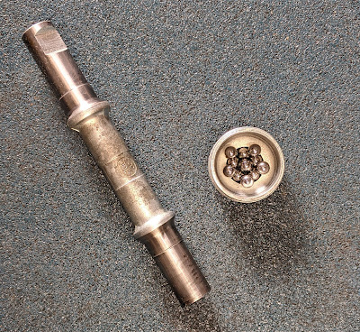
And I finish with some photos of the BB shell, axle and cups, apart and reassembled. The axle is 14.2cm long, and measures about 6cm between cones. There are 11 balls of 1/4" on each side. It's clear that this bike was not much used, which makes it a great candidate for a clean up and service. Restoration using as many of the original parts as possible.
I think the drive side cup is welded in - in any case, I didn't bother trying to remove it. Now I just need to find some new cotter pins, which as far as I can tell are 3/8" in diameter. Whether or not it's considered right, I WILL use some copper anti-seize when I fit them.


No comments:
Post a Comment